
 Likes:


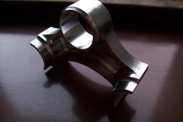
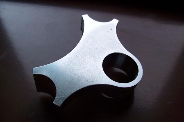
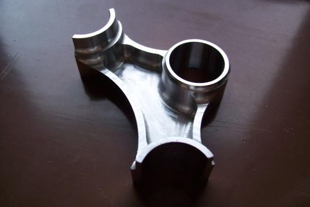
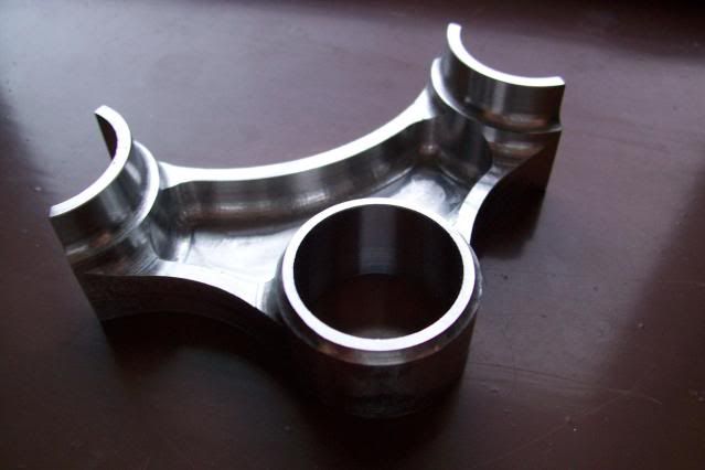
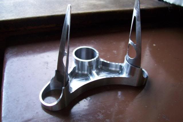
I was going to post this on FNL.. but I feel I should show the design here instead.. I need a gut check concerning the design and am asking you fine folks to offer thoughts if you feel so inclined.
I will share the thoughts I have later, but for now I feel that I am thinking too much about it.
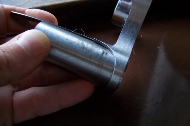
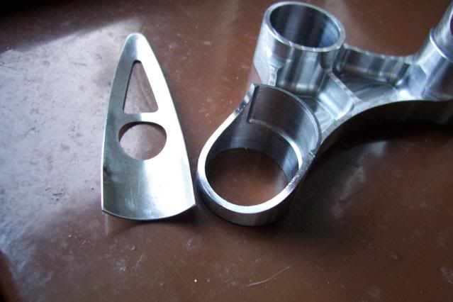
The crown is designed for 25.4mm round blades .9/1.3 wall and 25.4mm threadless steerer. I plan to use a SON20 disk compatable dyno. Cut from 1" 1018 plate. This crown is for a Chicago style winter bike I am designing. If it turns out to be a faulty design then I will start over... not proud here!
Thank you for your time,
CWN

 Reply With Quote
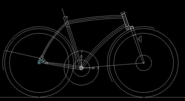

Bookmarks