Dear Guest,
Please register or login. Content don't create itself!
Thank you
-
 Re: Lyrebird Cycles

Originally Posted by
Mark Kelly

I'd be really interested to see how my techniques work out building a bike your size.
IMO they are unlike anything else. This thread is about why.
People who come to one off a metal bike tend to remark on the Lyrebird being smoother and flowing over the surface better.
People coming to them off carbon tend to remark on the Lyrebird feeling lighter and more responsive.
One thing no-one's ever said is that they feel "wooden".
There are several of us at the far right side of the bell curve on height. We all chip in and move it around the country!!!
Mike
Mike Noble
-
 Re: Lyrebird Cycles
Interesting read.
Im curious about the waveform thought with consideration to other metal bikes of ranging tube sizes, thicknesses and butt lengths now. since most frames are built of the same metal with all different sized tubes in the front triangle and the chain/seat stays also being different size and thicknesses.
On average, how long have you had to spend on each frame to develop your approach for frame size/ materials and material location before you even grab a knife/saw/file?
Matt Moore
-
 Re: Lyrebird Cycles

Originally Posted by
mnoble485

There are several of us at the far right side of the bell curve on height. We all chip in and move it around the country!!!
Mike
If you can marshall your fellow four sigmas*, I'll do it. Don't forget to include Josh.
Mark Kelly
-
 Re: Lyrebird Cycles

Originally Posted by
Hellafab

Interesting read.
Im curious about the waveform thought with consideration to other metal bikes of ranging tube sizes, thicknesses and butt lengths now. since most frames are built of the same metal with all different sized tubes in the front triangle and the chain/seat stays also being different size and thicknesses.
There will be more on this in a couple of following posts, but yes, the thinner the shell the more easily it buckles and the more it resonates like a drum skin or the arched top of one of Lou's guitars.

Originally Posted by
Hellafab

On average, how long have you had to spend on each frame to develop your approach for frame size/ materials and material location before you even grab a knife/saw/file?
Far, far too long, I really need to get quicker.
True to the 'nik that TT granted me, I am finding the process of marshalling my thoughts to get them into (at least partially) comprehensible prose is helping to clarify what's important.
Mark Kelly
-
 Tubes Part 1
I've split this into two to make it (hopefully) a little easier to digest, The first part contains a lot of data on which the decisions I describe in the second part depend.
Metal tubes are basically pretty simple: metals are isotropic and all the ones used for bicycles have about the same Poisson’s ratio, so the factors that influence the mechanical performance of a metal tube are its size and shape, the material from which it is formed and the distribution of wall thicknesses. This makes things nice and predictable: for any of the metals used in bike frames the shear modulus, which governs torsional stiffness, will be a constant fraction of the Young’s modulus*, which governs bending stiffness. Since the Poisson’s ratio is around 0.3 this fraction will be around 1 / 2.6 ; as an example for a standard Ti alloy (3Al 2.5V) E = 95 GPa and G = 36 GPa.
With fibre composites everything changes: the properties of the fibres depend on the orientation of the molecules from which they are made so the fibres themselves are anisotropic. The properties of the composites in turn depend on both the fibre and matrix properties and the fibre orientation in the matrix, adding further complexity.
For carbon fibres along the axis the ratio will vary according to the type of fibre: for Toray T300, a standard modulus fibre, it is about 1 / 13 (E=230 GPa, G = 17 GPa) while for Rayon T-75, a high modulus fibre, it is about 1 / 39 (E= 540 GPa, G = 14 GPa). These are raw fibre values, the fibre is usually between 50 and 70% of the composite so whole composite values will be less.
If these same fibres are layed up with a different orientation, the ratio changes again. A good example is a 45 / 45 orientation, which achieves the highest torsional stiffness at the cost of lowering the bending stiffness, so the ratio ends up roughly 1 : 1.2 . The influence of fibre type is surprisingly small: the T-300 fibre will give around 24 GPa in torsion while changing to T-75 will increase this to around 26 GPa, so a 135% increase in fibre modulus thus gives less than 10% increase in torsional stiffness.
This is largely due to a matrix effect where the resistance to torsion depends to a great extent on the ability of the matrix to prevent the fibres sliding past each other. Since the matrix has much lower stiffness than the fibres the distortion of the matrix dominates over the extension of the fibres. This effect can be exploited for good and not for evil, see a later post on the “Low C” project.
Wood is, of course, a fibre composite material already; the fibres being semi-crystalline cellulose fibrils and the matrix being a combination of hemicellulose and lignin. The modulus of the cellulose fibres depends on the degree of crystalinity and can reach 90 GPa and of course it’s very light, so pure crystalline cellulose fibre is almost at carbon levels of stiffness to weight and more than twice as good as Al, Ti or steel.
A significant difference from other composites is the internal arrangement of these components: the wood is made up of long thin cells and the fibre fraction is in the cell walls. In hardwoods there is further microstructure as the cell wall is composed of several connected layers. Within this microstructure there are nanostructures: the growth of the cell wall lays the fibres in a helical pattern rather than them being simply laid in straight lines as in a mechanically fabricated composites.
The end result of this is that properties of the wood composite are quite different from the properties that would be obtained with an equivalent percentage of straight cellulose fibre in matrix: the Young’s modulus is lower but the shear modulus higher and it is considerably more resilient and tougher. The Eucalyptus spp woods I use have E between 16 and 24 GPa and G about 2 - 3 GPa so the ratio between them is about 1/8. The matrix effect on torsional stiffness is also much less marked so a 45 / 45 overwrap of thin wood laminae can achieve about 10 - 12 GPa.
Manufactured natural fibre composites such as flax or the new BioMid spun crystalline cellulose fibre have properties between those of the carbon composites and wood.
An easier summary of all this is contained in these graphs which I prepared from data in "Experimental Techniques and Design in Composite Materials"
edited by M.S. Found supplemented by my own observations. Any mistakes are my own.
The data is given as specific moduli eg the actual modulus divided by the density of the material, so the axes are scaled x 10^6 m^2 s^-2. Fibre composites are assumed to have 65% fibre volume. Since these are specific moduli there's no real differnce between Al, Ti and steel so I've lumped them under "metal", with the data presented as a line where it’s really a single point as there is no dependence on fibre direction.
(correct graph in next post)
* See post #3 for definitions and relationships between these two moduli and the Poisson’s ratio.
Mark Kelly
-
 Re: Tubes Part 1
There's a huge mistake in the graph above: mods if you could delete it I'll post the corrected version tomorrow.
Mark Kelly
-
 Re: Lyrebird Cycles
I would volnteer to test the left side of the bell curve ;-)
-
 Re: Lyrebird Cycles
Corrected graphs

Modulus Graphs
Mark Kelly
-
 Re: Lyrebird Cycles

Originally Posted by
bontie

I would volnteer to test the left side of the bell curve ;-)
My wife is already on that job.
Mark Kelly
-
 Re: Lyrebird Cycles
Way to bring it full circle M.K. Again, this is alot of information to consume. The peek into your process is pretty compelling stuff.
As consumers we know what we like, you explain why it is so.
-
 Re: Lyrebird Cycles
Thanks for the compliment but I must demur: at best I can explain why I think it is so.
Mark Kelly
-
 Tubes: Part Two
Given the above, there is obviously a huge field of possibilities for any tube layup so my first job was to whittle this down a bit.
It became obvious when I was experimenting with layups that the inner layers had to have fibres in the “hoop”; if they are oriented axially there is a high risk of delamination when the tube is stressed. Some years ago when I was working for a food manufacturer as a process engineer I visited the factory that made our boxes, they also made such things as the core rolls for toilet paper. These are made by winding strips of cardboard around a cylindrical former and slicing them to length. I adapted this idea using wood laminae and counterwinding the helices to improve torsional rigidity. I then added an inner layer, initially in lightweight glass, as a method of ensuring that the inside of the tube was completely sealed against moisture. I then played with various methods of adding extra layers of carbon and wood in different amounts and orders of layup angle and “clock” around the tube and testing the results for strength and for acoustics, often the same way: I hit them with a hammer and listened to the resulting sound. The sound of splintering carbon was considered a failure.
BTW the sound of splintering wood was much less common, the wood composite construction is far more impact resistant than straight carbon. I quickly came to the conclusion that the less carbon there was the better the tube sounded, so all tubes are now less than 50% by weight carbon composite. Since carbon composites are roughly twice as dense as the wood laminae, this is equivalent to less than 30% carbon composite by volume. I try to avoid using carbon laid in the axial direction and substitute it with boron fibre composite wherever possible. The only manufacturer of boron fibre in the world is in the US and it is literally weapons grade: it’s around ten times the price of carbon and obtaining it involves an amazing amount of bureaucracy including having sign a document saying I wasn’t going to sell it to North Korea
Another constraint on boron composite is that trying to cut, grind or sand it post cure results in thermal degradation of the matrix and / or the production of thousands of incredibly painful tiny splinters that get into everything (including the other members of my family), so the above does not apply to areas of the tube that are cut back for joint mitres. Besides sounding better, a major bonus to using boron is that it is far stronger in compression than carbon due to the boron fibres themselves being much large diameter and thus less prone to kinking.
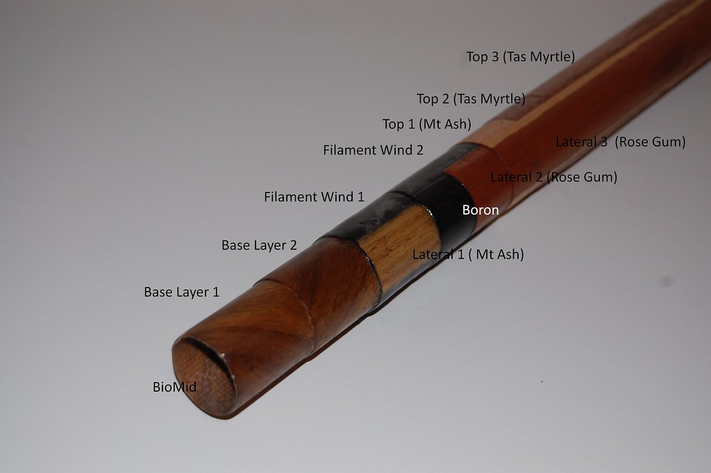
The general pattern for tubes which are primarily loaded in torsion (down tube and top tube) is similar to this demonstration tube I made for the Melbourne Custom Bike Show:
Baton Explained
The base layers are as already discussed, except that I’ve dropped the glass liner and now use the superb BioMid spun crystalline cellulose fibre as the inner layer. The choice of woods for the inner layers is somewhat constrained in that some of the woods I prefer elsewhere don’t take to a tight radius bend happily; for instance E. regnans* (Vic. Ash) has a habit of splitting along the grain which makes it difficult to align the edges of the strip correctly. This reduces the choice of available Australian hardwoods to about a thousand. I’ll generally use one of E. maculata (spotted gum), A. mearnsii (black wattle)* Nothofagus cunninghamii (myrtle beech) or Toona ciliata (Australian cedar) in descending order of stiffness and strength (and density). BTW Australian cedar isn’t a cedar at all, it’s actually a hardwood, more closely related to mahogany than anything else.
I then wind at least two layers of carbon using my filament winder. Winding my own tubes this way allows an extraordinary degree of control over the properties compared to standard prepreg layup techniques: I can control the number of layers and the fibre type, fibre direction and the effective thickness of each layer. This last is achieved by varying the spacing of the wind to between 100% and about 65% of the width of the tow, creating an overlap which allows the thickness of the wind to vary by up to 50% (any higher and the wind starts getting uneven which creates resin rich areas).
I generally use an aerospace spec IM fibre, currently my go-to fibre is Hexcel’s IM9. I do not use HM or UHM carbon; partly because most of the carbon is wound at an angle so I would gain very little in stiffness due to the matrix effects mentioned above but mostly because of the poor strain to failure performance of the UHM carbon. If you plot the strength vs stiffness of the various available types of carbon, they mostly lie on a straight line with a slope of 1 : 50 eg each type has a tensile strength about 1/50th of its Young’s modulus: another way of saying this is that each has a strain to failure of about 2%. Once you get past about E = 300GPa, however, the line flattens and then eventually reverses, so UHM carbon often has a strain to failure of 1%, sometimes less. This has three principal effects. Firstly it makes the composite very fragile as it cannot flex to absorb impact energy. Secondly it means sailing very close to the wind on fatigue failures as it’s not uncommon to see strains of about 0.5% in bike frames and a safety margin of two is generally considered inadequate. Thirdly and most importantly, it effectively makes no contribution to the strength of the composite when it is combined with materials which have higher strains to failure (and everything else has a strain to failure of 1.9% or better) .
To see why this is so, consider what happens as the composite material is stressed. The stress causes the material to strain and the material which has the highest ratio of stress to strain (eg the highest modulus) naturally takes more stress at a given strain, reducing the load on the other materials. As soon as we reach the strain limit of this high modulus material, it breaks, so the stress it was carrying is suddenly distributed to the other materials. To prevent catastrophic failure, we need to design the composite so the other materials can carry the full load without the contribution of high modulus material and once we do that we might as well make the thing without the high modulus material in the first place.
I usually interpose two or more part layers of axially oriented wood and boron between the carbon layers**. These part layers each have a width of about a quarter of the tube circumference and are placed on the laterals of the tube. These layers act as acoustic constrained layers which modify the acoustic response of the whole tube, they also slightly increase the radius of action of the layers on the lateral surface of the tube compared to the central surfaces.
The final wood layers are then laid down, with the lateral layers laid up first then the medial layers which are laid so they slightly overlap the edges of the lateral layers. This overlap is then scraped and sanded back to bring the tube back to round, resulting in the edges of the medial laminae forming an angle at the tube surface. This is a consequence of the differential layering back at the carbon stage but I also exploit it to show off the sheer beauty of the woods I use.
The woods for these layers are chosen for mechanical, acoustic and aesthetic reasons: for the lateral layers my go to wood is E. grandis (rose gum), primarily for its excellent stiffness to weight ratio. I’ve also used E. sideroxylon (red ironbark) and Nothofagus cunninghamii (myrtle beech). These were used on bikes for my wife and myself, the first because when our children were growing up we spent a lot of time in the box ironbark forests of NE Victoria and the second because it’s the favoured habitat of the lyrebird in the montane forests of Victoria. My wife came up with the idea of using woods withan emotional significance and I think it’s a great idea.
For the medial layers I usually use a combination of woods, a typical layup would be a single layer of E. regnans (Vic. Ash), lighter than the E. grandis but almost as stiff, then two layers of A. Melanoxylon (Tas. Blackwood), generally considered the queen of Australian tonewoods.
The colour contrast between these layers is not an accident.
*Since there are so many species of Eucalyptus and Acacia here, I generally won’t bother typing the genus names for these and just use E. and A. respectively.
**The eagle eyed will notice that the demonstration piece was made with the boron layer outside the last carbon layer, I’ve since swapped this order.
Mark Kelly
-
 Tubes: Part Three
The last one was long on words and short on maths, this one is long on both. Bear with me, there are some interesting figures at the end.
In the screed above I’ve mentioned that I have a great deal of latitude on several processes that affect the torsional and bending stiffnesses of the tubes, such as the number, fibre type, winding density and winding angle of the carbon layers and the number, wood type, grain direction and radial orientation of the wood layers . This allows me to design each tube to suit its intended purpose, which is a nice statement but what does it actually mean?
Basically it means that I establish design criteria for a given tube, then I try to make a tube that fits the criteria chosen. Generally, one criterion is to make the lightest tube that satisfies the other design criteria but this is not definite, for instance on my wife’s bike she was happy to accept a 20g weight penalty to allow the inclusion of a wood that has emotional significance to her.
The other design criteria naturally depend on where the tube is going to be used; to keep this simple but reasonably illustrative I will focus on the criteria for a typical road bike top tube. For a tube like this I am looking for torsional and lateral bending stiffnesses that result in an appropriate degree of front end torsional stiffness for the frame as a whole, lateral stiffness that is appropriate for the rider’s weight and aggressiveness and a high ratio of lateral to vertical stiffness.
To assist with this process, I’ve set up a design spreadsheet that calculates the mass and the contributions to torsional stiffness and the lateral and vertical beam stiffnesses of each layer or part layer using the moduli given in the graphs in part one of this series. This involved a bit of calculus as none of the standard sources give a moment of inertia for a tube with the sides sliced off, so I had to calculate that myself . Since others might find this useful, I’ve included the formulae I use below.

Sections
“J” is the rotational moment of inertia, “Ixx” is the moment of inertia about the X axis etc.
As a reality check: as r -> R, (R^2 + r^2)/2 -> r^2 ,
so 0.410.A/2.(R^2 +r^2) + 0.090.A/2.(R^2 +r^2) = A/4 . r^2
which is the classic formula for the moment of inertia of an infinitely thin hoop.
The spreadsheet then adds all the contributions to give a total calculated value for torsional, lateral and vertical stiffness of the tube.
The model I use for relating these individual tube stiffnesses to the stiffness of the frame as a whole is probably a little simplistic but it seems to achieve a reasonable fit to reality. I can’t afford FEA and it apparently copes badly with organic materials on the small scale so this is as good as you are going to get. For the front end stiffness, I simply sum the contributions from torsional stiffness and beam stiffness of each of the top tube and down tube. This is based on the following thought experiment:
Imagine the top tube is rigidly joined to the head tube but the down tube connected via a ball and socket joint so it can swivel. To twist the head tube away from the seat tube axis by a given degree then requires overcoming the torsional stiffness of the top tube in series with the lateral beam stiffness of the down tube. Symmetry requires that the same thing will obtain with the positions reversed, so the four factors TT torque, DT beam, DT torque and TT beam are summed to give the frame tubes’ contribution to front end stiffness.
Note that this does not account for the contribution of the joints to the headtube or the headtube itself. In practice calculating the figures on the “free length” of the tube eg the length between the actual joints yields overall stiffness figures which seem close to the real world frames tiffness. In the future I hope to refine this but that will wait until I build the frame fatigue / stiffness testing rig later this year.
Evaluating the contribution of the torsional stiffness of each tube is simple, just apply the known formula for angular deflection:
Θ = T L / J G,
Rearranging gives :
T / Θ = J . G / L
eg for a given torque and a given product of rotational moment of inertia and shear modulus, the net deflection will be proportional to tube length. This seems intuitively obvious.
Please note that Θ will be in radians and the formula assumes the torque is applied along the axis of the tube. If the torque is applied off axis we can simply multiply by the sine of the angle between the torque force couple and the tube axis.
Evaluating the contribution of the beam deflection of each tube is a little more complex, fortunately we have the great Leonhard Euler on our side. He observed that the angular distortion of each section will be proportional to the torque on that section, which is in turn proportional to the ratio of tube length to moment of inertia; all these sections add so the total angular displacement is proportional to the distortion per section times the length and finally the net linear displacement is the integral of these angular displacements over the length. Euler’s formula for a point loaded cantilevered beam is:
Δ x = F . L^3 / 3 . E . I.
Now consider the headtube with a length between tube junctions of Y.
A torque T will produce a force couple F acting at distance Y, so
T = F.Y or F = T/Y
A deflection of Δ x at one end of the tube is equivalent to an angular deflection of
Δ x / Y, so
Θ = Δ x / Y or Δx = Θ . Y
Substituting these into the formula above gives
Θ . Y = T/Y . L^3 / 3 . E . I.
rearranging gives
T / Θ = Y^2. 3 E I / L^3.
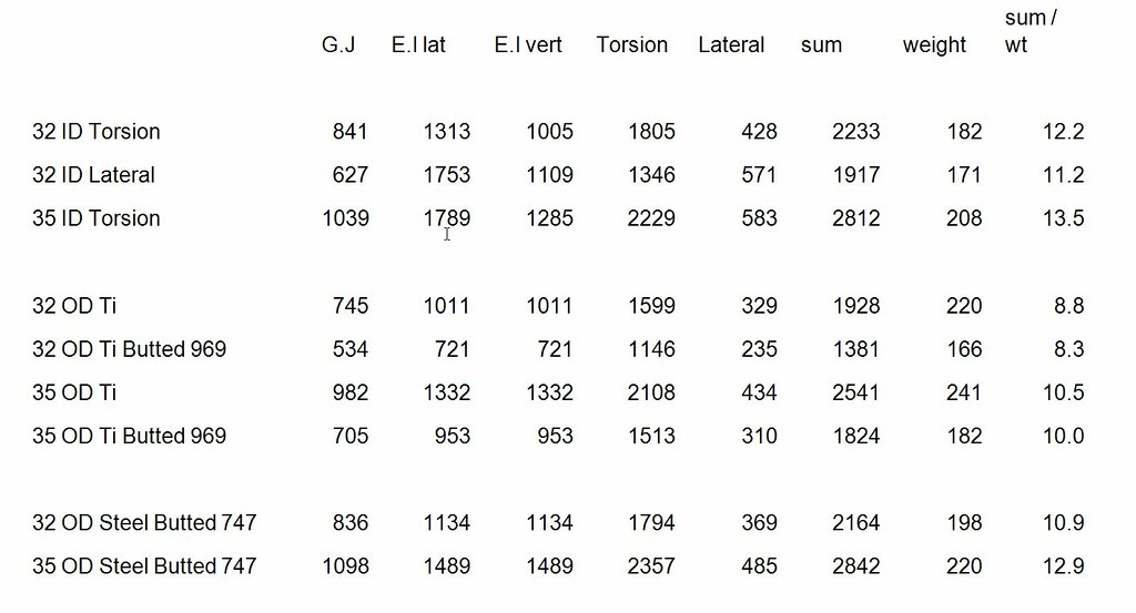
To see who this works in practice, here are the calculated stiffnesses for some tubes. These were options for the top tube on a bike for a fairly large rider (that would be me). To give you an idea of how these figures stack up against other materials, I have included figures for tubes of other materials:
Figures
Mark Kelly
-
 Re: Tubes: Part Three
wow.
too much to consume.
fly paper + algebra + makIng + australIan natIves = wow / graph x n+1
John Hall
biasworkshop.com
-
 Re: Tubes: Part Two

Originally Posted by
Mark Kelly

the sound of splintering wood was much less common, the wood composite construction is far more impact resistant than straight carbon.
I inadvertently tested this to the max today.
My wife and I went for a ride over Mt Macedon today, drove out to Gisborne and did the loop then drove back, so we had the bikes on top of the car when we decided to duck in to the local shopping centre to get some things for lunch.
Yep, you guessed it, we drove straight in to the car park having forgotten about the bikes.
It seems that the bikes are stronger than the bike carrier which was pried straight off the roof rack with one bike still attached. The other bike hit the dangle bar first and just pushed it out of the way.
I feel like a goose; I'm up for a new bike carrier and possibly a left ergolever but that seems to be the extent of the damage. It could have been far far worse.
Don't try this at home.
Mark Kelly
-
 Acoustics Part 3
OK it's time to try to tie all this together. As I’m sure you are expecting by now, this will start with a dissertation on a subject that seems only peripherally related before getting to the central point. In this case that subject is the physiological basis of human sensitivity to vibration.
Vibration is primarily sensed through three types of mechanoreceptor located in the skin, each of which covers a different range of frequencies. The lamellar or Pacini’s corpuscles have a peak sensitivity at about 250 Hz (around Middle C), Meissner corpuscles have a peak sensitivity around 50 Hz (around the G two octaves and a fourth below Middle C) and Merkel cells have a peak sensitivity around 10 Hz (below the range of human hearing so not normally given a note but it would be the E almost five octaves down). The first two show a classic bandpass response with a single peak and first order (3 dB / octave) decline in sensitivity either side of these peak. The last has a lower and flatter response and correspondingly slower roll off. Putting all three together, sensitivity to vibration follows a biphasic curve as below. Importantly, the relatively slow rolloff means there will still be significant response a decade or more past the upper sensitivity maximum.
Sensitivity_Spectrum
Curve taken from a paper by Oey et al
These receptors respond to deformation (eg stretching) of the skin surrounding them, repeated deformations are interpreted as vibration. The sensitivity to vibration of these structures appears to have evolved to allow sensing of the surface textures of objects, so the receptors are concentrated in areas like the hands and fingers where this is most useful. As the hand or finger is brushed across a surface, the ratio between the speed of the repeated pulses from the receptors and the speed of the finger or hand across the surface indicates the spacing between surface features. This ability to discriminate texture survives even when the hand is holding a tool, since the vibrations propagate through the tool and are then sensed in the normal way.*
I believe the same process underlies the ability to “feel” the road surface when riding.
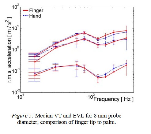
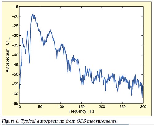
Looking at the data from various studies of shock response of bicycle frames, eg those published by Champoux et al and Hastings et al : the road reaction forces peak at around 30Hz and decline fairly steeply thereafter:
Champoux_Spectrum
This curve is taken from the Champoux paper and appears to be in logarithmic units (decibels) so the energy present at 200 Hz is approximately 1 / 1000 of that at 30 Hz. The lumpiness of the curve is a consequence of it being a spectral breakdown of the transducer signal per Fourier transform.
The primary mechanical vibrational modes of the frame were also determined by Champoux: considering frame modes only (eg ignoring fork and handlebar modes) one of them, the frame torsional mode, occurs at about 50 Hz; all the bending modes are at 300 Hz or higher. In turn if we consider the acoustic resonances of the frame itself, the following table gives the lowest frequency at which such a resonance can occur in frame elements of 600mm length: this is the frequency at which the element is one quarter wavelength, see post #8 above for why this occurs and why the P wave and S wave velocities (and therefore minimal frequencies) differ.
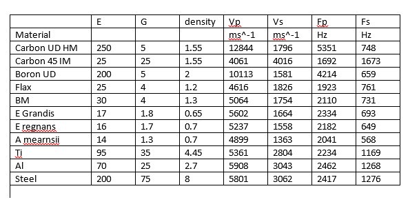
Frequencies
As I’ve said before, damping is simply the loss of energy on deformation and the damping factor for a given material is the ratio of the energy lost to the energy stored (and then given back). It follows that damping is not universally either good or bad but depends on the source and sink of the energy that is lost. In turn, for the case of high performance bicycles, the desirability of any energy loss depends on the frequency at which it occurs. As I hope I have shown above, the responsiveness of the bicycle is a result of its response to low frequency deformations such as pedalling forces and the wheel reaction forces so damping in this frequency regime is undesireable. Higher frequency energy on the other hand is largely noise, so damping in this regime is desireable. The turnover would appear to lie somewhere between the frequencies of the road reaction forces and the frame torsional response at around 30 – 50 Hz and the frequencies of the frame bending modes and the maximal response of the body to induced vibration at around 250 – 300 Hz.
Most materials have no significant relationship between damping factor and frequency response: most metals** have a low damping factor at all frequencies of interest whilst carbon composites have a high damping factor at all frequencies, how high depends on the properties of the matrix as explained previously.
It appears that one of the criteria on which tonewoods were selected is that the damping factor changes with frequency. If you look at the data on tonewoods in Follmann & Sons - Tonewood , São Paulo, Brasil you’ll see that the damping is at a minimum from DC to about 150 Hz and rises increasingly steeply thereafter.
This is normalised data and it’s for South American tonewoods but Australian tonewoods follow a similar pattern. This of course fits neatly with the properties outlined above; that's not an accident.
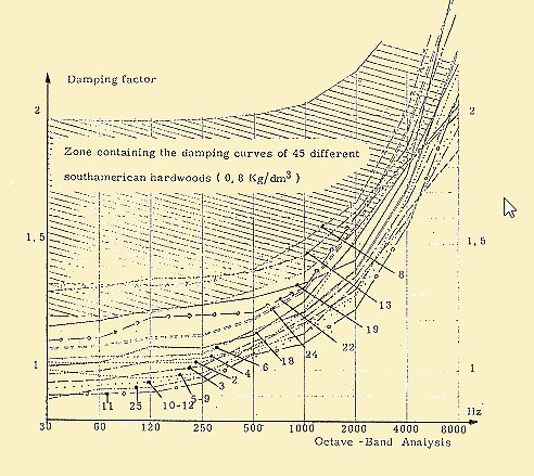
Tonewood damping
Putting all of this together, it appears that the incorporation of tonewoods in a manner which allows them to dominate the acoustic response of the frame achieves a unique balance of properties: the perceived responsiveness and connectedness of the bike on the road is improved by minimising the loss of energy in the range of frequencies which correspond to these desireable properties whilst the perceived harshness and chatter of the bike is diminished by maximising the loss of energy at these undesireable frequencies.
That’s my theory for now, I’ll stick to it until better information comes to light.
* You can confirm much of the above by holding a stick and swiping the end of it over a rough surface and a smoother surface at different speeds, say textured pavers vs smooth concrete. The texture of the rough surface will be perceived as more or less constant at different speeds whereas with the smooth surface there will be a speed above which the perception of texture diminishes sharply: this is the speed at which the pulse frequency starts heading down the sensitivity curve.
** the exceptions are mostly specialised alloys such as shape memory alloys, although certain magnesium alloys also have relatively high damping factors.
Mark Kelly
-
 Elliptical (aka ovalised) tubes
I was reading 44’s SO and his use of laterally flattened chainstays got me thinking about the way that shaping tubing alters its characteristics. This, in turn, got me thinking about how we can work out how large the effect actually is. Being me, I decided there’s no substitute for maths, so here we go.
I’m going to model the tube as an ellipse which has been flattened from a tube of standard outside diameter which means the overall circumference remains constant. There is no exact analytical solution which will allow us to compute the lengths of the minor and major axes in this scenario so I will use Ramanujan’s second approximation:
ellipse-perim-a3.gif
where the factor h is given by
h = (a - b)^2/(a + b)^2
The error in this approximation is h^5, so for a/b =2, which gives h = 1/9, the error is 1/9^5 which is about 0.002%, good enough for jazz.
In terms of the original tube diameter, C = pi . D, substituting this into the Ramanujan equation and rearranging gives:
a + b = D / (1 + 3h / (10 + Sqrt(4 – 3h))).
For a given ratio between major and minor axes which I’ll call n:
n = a/b
so a + b = a . (n + 1)/n
substituting and rearranging gives
a = D . n / (n + 1) (1 + 3h / (10 + Sqrt(4 – 3h))) and
b = D / (n + 1) (1 + 3h / (10 + Sqrt(4 – 3h)))
The moment of inertia of an ellipse around the minor axis is given by
(Pi/4) (a^3.b)
and around the major axis is
(Pi/4) (a.b^3).
For a tube of wall thickness t, the dimensions to the inside wall are a1 = a - t and b1 = b – t, so the moments of inertia for the tube cross section are
(Pi/4) (a^3.b – a1^3.b1) and
(Pi/4) (a.b^3 – a1.b1^3)
By the perpendicular axis theorem, the polar moment of inertia is the sum of these two.
Reality check: if a/b is set to 1 (eg the tube is round) the equations give a = b = D/2 = r and the moments of inertia are both equal to Pi/4.(r^4 – r1^4) which is the known formula for an infinitely thin hoop.
To enable practical comparisons of the effect this will have on tube shaping, I wrote a little spreadsheet that calculates the lateral, vertical and torsional stiffness of an elliptical tube compared with those of the same tube before squishing and computes the contributions of said tubes to the overall frame stiffness. The model I used here has already been dicussed in this thread. I used a range of ovalisation ratios from 1 : 1 (eg an unmodified tube) to 1 : 2 .

Ellipses
Note that the elliptical tubes show in increase in lateral stiffness but a decrease in torsional stiffness. In this particular application the net effect is a fairly small increase in overall stiffness which is maximal at the 1 : 1.5 ovalisation ratio, above which the loss of torsional stiffness overcomes the increase in lateral stiffness.
In other applications (such as 44s chainstays) the results will be different. Also please note that ovalisation could be of benefit in other aspects of the design: designers may wish to avail themselves of the reduction in vertical stiffness or it may be used to improve the matching between a medium diameter top tube and a larger diameter seat tube, or simply to improve the “portability” of a cross bike for instance.
Mark Kelly
-
 The Low C Project
The tonewood project is primarily about ride quality but there are many other factors worth considering, one of which is the greenhouse gas impact of my activities and opportunities to reduce this. To see what effect I could have on this, I embarked on what I called "The Low C Project" (geddit?)
First, we need data. The following table gives GHG equivalents in kg CO2 / kg material for common bike building materials. I’ve used data culled from several sources including the Argonne National Laboratory’s excellent GREET data

GHG Table_1
Notes on the data: I have been unable to find any public data on boron fibre, even the manufacturer was unable to supply the required information, so I’ve guessed it’s somewhere around carbon fibre. In the end it’s a small percentage of the total so I’m not too concerned about this.
The values for the Ti alloys and particularly the spread of values, apparently the spread is partially due to the vanadium content: 4% vanadium contributes about 12 kg/kg.
The value for wood depends on the lifecycle considerations taken into account and the degree of processing, in this case it is for Australian hardwood, air dried and processed to veneer leaf so the processing cost is line ball with the CO2 capture during growth.
Plugging these values into a typical Lyrebird frame build gives the following breakdown:

Low C_1
These figures do not include process costs, which are dominated by the approximately 20 kWh of electric power used, mostly in the oven. My local electricity supplier quotes a GHG equivalence of 1.3 kg/ kWh, reflecting the dominance of filthy brown coal in Victoria’s energy supply, so that adds about 26 kg. I hope to address this by adopting solar power for the oven in the next year or so. The enormous amount of plastic waste from such things as vacuum bags should also be take into consideration, this adds a further 4 kg (approx.). I don’t know what I can do about that.
The greatest reductions in the construction itself would come from reducing the amount of carbon fibre used, followed by replacing the titanium hardware and moving to a “bio resin” based epoxy.
Taking the last first: at the present state of play this isn’t going to happen until the “bio” epoxies improve: the available high “bio” content epoxies are not formulated for use as laminating resins and the available “bio” laminating resins are less than 20% renewables. This means the available reduction in GHG per frame is less than 1 kg, the trade off in lower resin properties is not justified by such a small reduction in impact.
Replacing the Ti hardware is easily done; at the cost of a small increase in weight I can easily use stainless steel fittings instead, they’re stronger and easier to bond anyway.
Replacing the carbon requires re-engineering the frames which starts with investigating the properties of biologically sourced fibres.
The most popular contender here is Flax, a bast fibre from the flax plant, but other possibilities include kenaf, hemp, jute, banana, ramie and the newly available BioMid fibre, developed by Gordon Shank in Canada and manufactured from recrystallised drawn raw cellulose from wood waste.
Here’s a comparison of some of these fibres, most of the data is taken from Pickering et al “A review of recent developments in natural fibre composites and their mechanical performance” Elsevier Science Direct
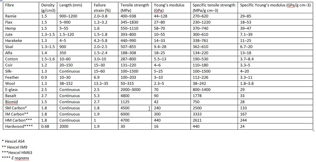
Fibre Poperties
Notes on the data: The natural fibres show extreme variability, a range of 3 : 1 in strength or stiffness between different samples of the same material being common. This is a consequence of their origin in the natural world and the variations in processing to which they are subjected. Another consequence of this is that the fabrics produced are often somewhat uneven in fibre lay and thickness, which exacerbates the unreliable physical data. A particular problem is that the uneven fibres do not lay straight against each other and this creates void space which absorbs resin: it is hard to get better than 50% fibre fraction in a natural fibre composite whilst 65 – 70% is achievable for carbon fibre etc. The strengths and stiffnesses given in the table are for the raw fibre, the useable strength and stiffness of a composites formed from one of these fibres is usually about half.
The Biomid fibre, being re-spun recrystallised cellulose, does not suffer from these problems: its properties and physical presentation are very consistent which makes it easy to use, it behaves a lot like a lighter version of glass fibre. The second thing to note is that nothing comes close to carbon fibre in strength or stiffness. Don’t be fooled by the apparent high strength of basalt fibre, when used in a composite with other materials which have about 2% strain to failure the useful strength is about 40% of the strength quoted.
The lower strength and stiffness of the renewable fibres creates another apparent problem: if we consider the axial strengths and stiffnesses, simply substituting say flax for carbon would require the use of 3-4 times as much flax fibre and given the reduced fibre fraction that in turn would mean using about five times as much resin. Given the GHG equivalence of the resin is about one quarter that of the carbon fibre, this would negate the saving we were trying to achieve. It would also result in a tube wall about 10mm thick. Engineering to the rescue.
Those of you who were paying attention at the start of this thread will remember that whilst the axial properties of CF far exceed those of other materials (boron excepted), this does not extend to the shear properties and thus to the torsional properties. You will also remember that in my comparisons of tube constructions, the torsional stiffness of the tubes is of paramount importance. The other engineering input is the comparatively large wall thickness of these tubes means we are not constrained by the probability of Euler buckling, a phenomenon which plagues very thin walled structures such as ordinary bike tubing, so we can increase the tube base diameter and thus increase the tube’s strength and stiffness. For any construction the strength scales with the product of weight and diameter while the stiffness scales as the product of weight and the square of diameter. Playing with these dimensions and feeding the figures onto the tube properties calculator I mentioned earlier, here’s a comparison between the standard tubes and the “Low C” tubes:

Low C Tubes
The frame I built to test these ideas is about 10% heavier than it would have been if built with my standard techniques but it is every bit as stiff and strong. Although it was built for a smallish woman, hence the 650B wheels, I’ve taken it for a few short test rides and there’s not a hint of noodle about it. It’s also the bike that broke the carrier off the car rack when we drove into a carpark with the bikes on top recently.
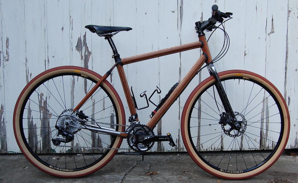
K-Bike
The ride of this bike is extraordinarily plush : given that it is shod with Grand Bois “Hetres” that is hardly a surprise. I was surprised by how fast and agile it is: I expected that I’d be able to overpower it but I can’t: the harder I stomp the faster it takes off. It’s a blast to ride.
Here’s a repeat of the table above for the new frame:
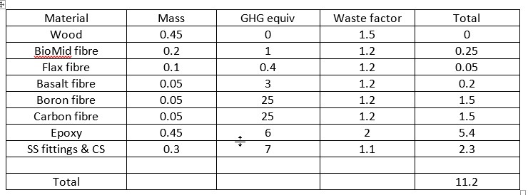
Low C_2
The greenhouse equivalence of the frame made from these materials is thus a little over half that of my other frames.
Mark Kelly
-
 Jig Development
My workflow dictates some requirements for a jig which aren’t met by any of the commercial jigs, so I’m stuck with building it myself. This will be my third: the first taught me a few things not to do; the second (this one) worked OK but it’s time to incorporate what I’ve learnt whilst using it into an updated and improved version.
The primary requirement for a jig is of course that it holds all the bits in the right places while the frame is being made, with the most important aspect of this being that everything is aligned to the plane of the wheels.
Since I use a curing oven and prefer to do most of the bonding and joint work with the frame in the jig, my jig needs to maintain this alignment when heated and cooled through cycles of +/- 100 C. I also need to be able to move the jig from the bench to the oven and back, so it needs to be light enough for me to carry and manoeuvre with a frame onboard without jostling anything out of position.
Looking at available jigs they are usually either plate jigs (eg Anvil, Sputnik, Henry James, the various old Italian boat anchors) or beam jigs (eg Bringhelli, Arctos, the various 80/20 jigs).
Plate jigs are built to be precise, solid, adaptable and easily adjusted but they are heavy, cumbersome and expensive. Whilst these jigs are fine for making bikes by traditional methods the weight and the support structures this entails make them too difficult to move into and out of a curing oven. They are also generally not designed to maintain alignment through the temperature swing of a composite cure cycle. They are expensive because they are made from many custom parts and were designed to allow the bike dimensions to be set without use of a CAD program, which made sense when such programs were a rarity.
Beam jigs tend to be simpler which obviates some of these problems but can make them less adaptable and more difficult to adjust. They can be made to be quite light and relatively cheap but this is generally at the cost of not holding alignment well, to combat this they can be beefed up but then they will no longer be light or cheap.
I’ve gone with a hybrid design with the aim of combining the features of both plate and beam jigs. The base of the design is two flat plates mounted on two horizontal beams with a third beam on a diagonal to triangulate the structure.
I used this basic structure in jig2 (referenced above) using laser cut 600 x 200 x 6mm extruded aluminium plates set at right angles to the beams. The problem here was that the laser cut plates were nowhere near flat as received so the whole jig was out from day one. I cross braced the back of the plates and added the diagonal brace to bring it into reasonable alignment but this time I'm going to start with flat plates at the beginning.
To this end I am co-opting the use of optical “breadboards” intended for aligning laser optics. These are machined from 13mm thick cast aluminium alloy tooling plate so they are extraordinarily flat and machined to fine tolerances, despite which they are available off the shelf for a surprisingly low price.
The breadboards are from Newport Optical, though similar (but not identical) boards are avilable from other makers such as Thorlabs. The jig is designed so that the planarity of the various parts depends on the flatness of the breadboards so excellent alignment can be maintained throughout.

Base_1
I used 80 x 40 beams top and bottom and set the plates so that the anchor points on each end align with the channels of the extrusion. A quick bit of trig gives the angle of the plate relative to the beam as 71.36 degrees which is within the typical range of head and seat tube angles, which serves to reduce the range of adjustment required. The beams are standard 8020 type extrusions, I used ones from Item though I got them through their Australian distributor. I went with black purely for aesthetics.
TBC.
Mark Kelly
-
 Re: Jig Development
The middle plate is fixed to the horizontal beams and functions as the datum centre of the jig; the forward plate slides to adjust front centre. Strangely, the mounting holes on the Newport plates are 7mm diameter not 6mm even though the counterbores are sized for M6 cap head screws: this creates about 0.5mm of slop in the standard mounting. Countersunk screws will centre themselves in the larger diameter holes but they won’t fit into the counterbore: ISO countersunk screws have larger diameters than the equivalent cap heads.
Since I didn’t want to butcher the optical boards, the easiest solution I found was to reduce the diameter of the countersunk heads until they fit in the counterbores. Since I use SS fasteners where possible anyway this is just a matter of chucking them up and grinding the outside of the cone down to 10mm. I applied the same thinking to the clamp screws but that required a bit of a left field fix: there are no countersunk clamp screws that I could find, so I used the conical ferrules out of 6mm Swagelok type tubing connectors to achieve the same end.

[url=https://flic.kr/p/GEUcJw]Fasteners
Before mods at top, after mods below. After these fixes there is less than 0.1 degree error in the angle of the plates WRT the beams, good enough for jazz.
Each of the plates bears an extruded beam which pivots on a bushing fixed via a screw into one of the preset M6 mounting holes in the plate and secured with Loctite. The pivots are in the same hole on each plate, this sets the horizontal datum for the jig: for convenience this is the axle line. For this first build I’ve used Iglidur bushings because I had some in my parts bin, I’ll eventually change over to bronze; although the Iglidurs are excellent the bronze will be stiffer and survive accidental overheating better.
As mentioned previously the plates are inclined at an angle of 71.4 degrees so the beams only need to pivot through a few degrees either side of this to provide a range of 68 degrees to 80 degrees for both head tube and seat tube angles. A pair of laser cut plates are used to set the angle of each beam and to hold the beam square to the plate. The outside edge of the plate is used as the reference for the angle graduations. In the original design these graduations were placed on diagonals to expand the spacing and make it easier to read, unfortunately this design fell foul of the limits of the laser cutter:
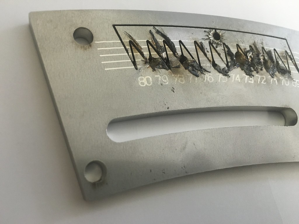
Laser limit
The laser obviously didn’t like trying to cut such acute angles in relatively thick and recalcitrant material (5mm stainless steel plate). This forced a redesign with the graduations along the arc, reducing the spacing, which can make it difficult for long sighted old farts. This can be eased a bit by placing a narrow flat strip through the slot above the graduations and resting it against the outer edge of the plate and reading the graduation below the strip.
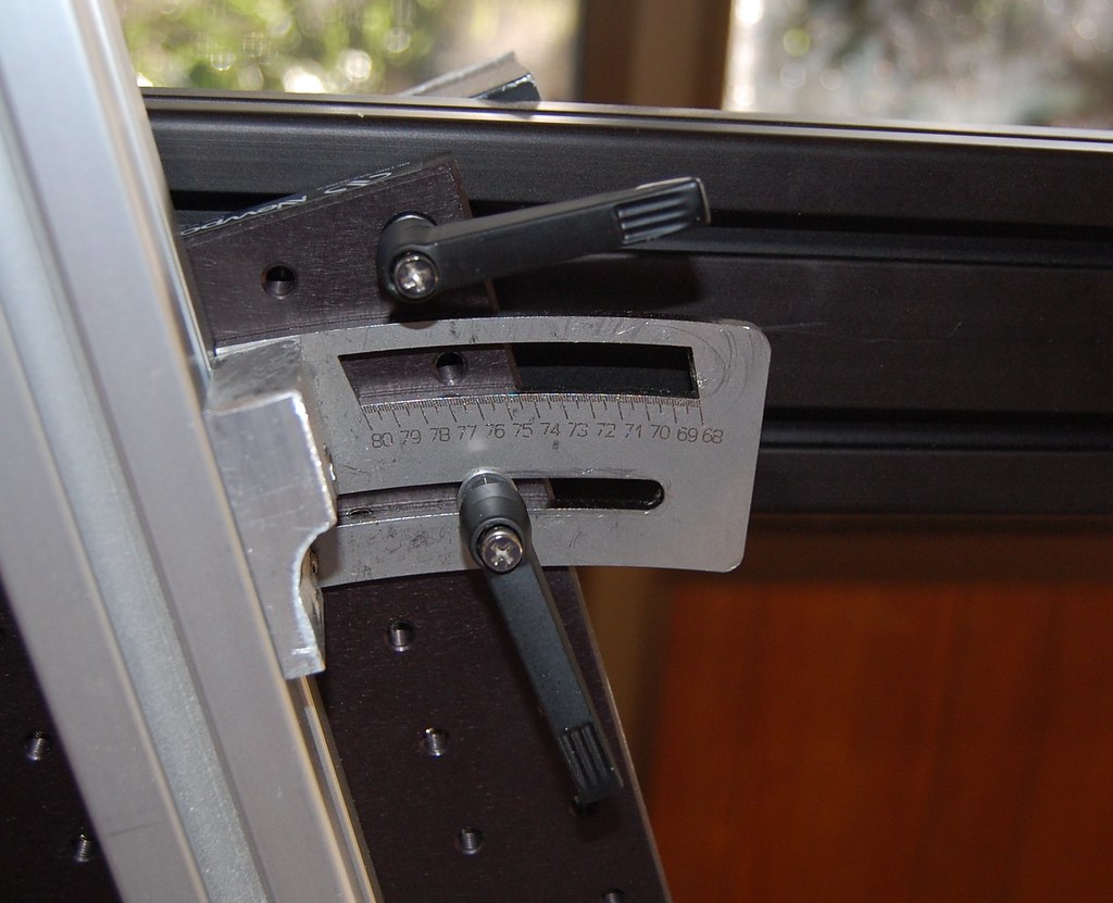
Angle Plate
I’m going to look at adding some form of line magnifier to see if that makes things easier, meanwhile I just need good light and to make sure I have my reading glasses on.
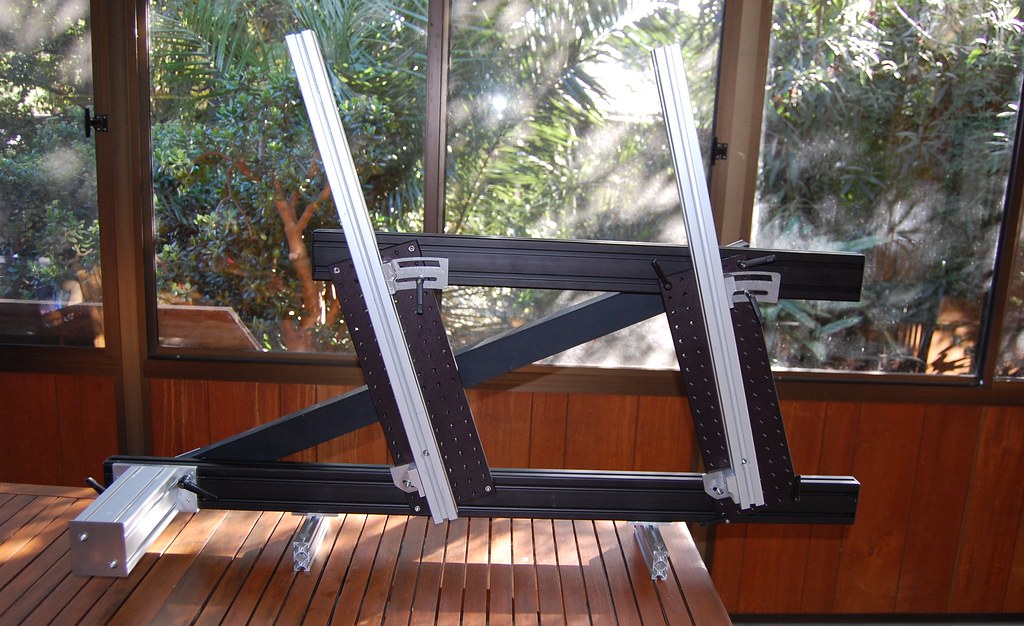
Arms_1
TBC
Mark Kelly
Similar Threads
-
By Boedie in forum Smoked Out
Replies: 30
Last Post: 11-22-2014, 05:45 PM
-
By magnoliacycles in forum Smoked Out
Replies: 25
Last Post: 04-11-2011, 04:57 PM
 Posting Permissions
- You may not post new threads
- You may not post replies
- You may not post attachments
- You may not edit your posts
-
Forum Rules
Bookmarks