Dear Guest, Please register or login. Content don't create itself! Thank you

User Tag List

Page 3 of 15 FirstFirst 12345678910111213 ... LastLast
Results 41 to 60 of 288

Thread: Lyrebird Cycles

  1. #41
    Join Date
    Aug 2011
    Location
    Beechworth, VIC
    Posts
    2,542
    Post Thanks / Like
    Mentioned
    10 Post(s)
    Tagged
    0 Thread(s)

    Default Jig Development, last part.


    Magnification

    A cheap plastic Fresnel lens solves the legibility problem.


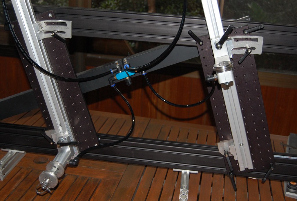
    Purge Hoses

    I decided to integrate purge fittings now rather than having to retrofit later.


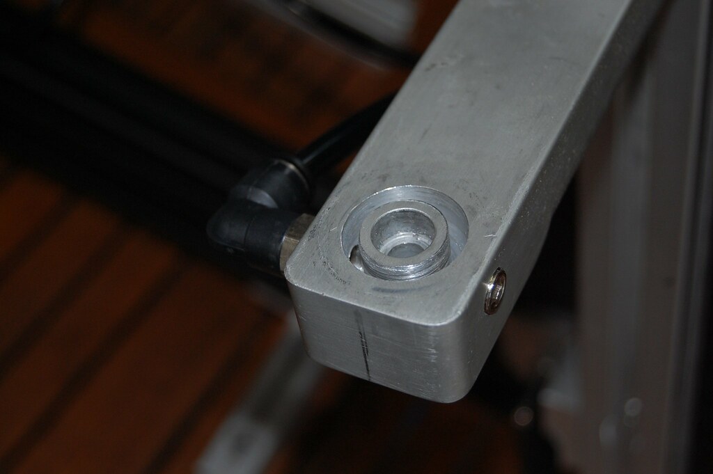
    Purge well

    So I cut annular wells into the support arms beneath the contact points, then drilled and tapped a gallery hole for a BSP gas fitting. On this arm I changed my mind about which direction I wanted the hose to face so I plugged the hole.


    Purge disc

    The support discs are stacked laser cut 5mm stainless plate, the vent holes placed to align with the well in the support arm. The design should help reduce the turbulence in the gas as it enters.


    BB Assembled

    The BB post uses a similar arrangement


    BB Discs

    Two of the holes are used to rivet the discs together using 6mm Ti tube leftover from the bottle cage project: gotta love the idea of titanium rivets. One of the discs for the outer puck has only these two rivet holes, these are tapped for M5 grub screws to prevent the gas escaping out the holes.


    Rear Arm

    After chopping and changing on the rear arm design I went with simplicity on the grounds that less interfaces mean less misalignment, it also reduces the number of pieces that need to be machined: the two 16mm blocks shown are placeholders for a single machined block which will have alignment grooves on the bottom surface.


    Rear Arm 2

    The dummy axle is off the shelf from Alex Meade, the dummy axle holder is a tube block off the shelf from PMW.


    Rear Arm 3

    The idea behind this arrangement is that the dummy axle and its holder stay in the frame, so there's a simple mechanism to allow release and realignment. This gets over the problem I had with the previous system (from Alex Meade) where I needed to realign the dummy axle every time I took the frame out of the jig.
    Mark Kelly

  2. #42
    Join Date
    Aug 2011
    Location
    Beechworth, VIC
    Posts
    2,542
    Post Thanks / Like
    Mentioned
    10 Post(s)
    Tagged
    0 Thread(s)

    Default Headbadge development.

    The original idea for this head badge was for it to be gold, silver and bronze so I started out using a copper base and played with silver and gold inlays using PMC. This turned out to be every bit as difficult as it sounds and the $100 per gram price on the 22k gold is a bit of a deterrent. The death knell was that once polished the contrast between the elements was not sufficient to show the detail of Chooey’s lovely avatar, so I turned to using just the silver.

    I decided to use four nines fine silver (99.99%) rather than the more common sterling silver as it has better resistance to tarnish and the lower strength is actually a benefit as it is easier to form to shape. After playing with a few alternatives I decided on a scheme of etching or chemically milling the design into brass sheet and using this to form the silver.
    First job is to transfer the design, using transparent film and an ordinary printer. Since the printer coverage is less than 100%, better results are obtained by overlapping two films.
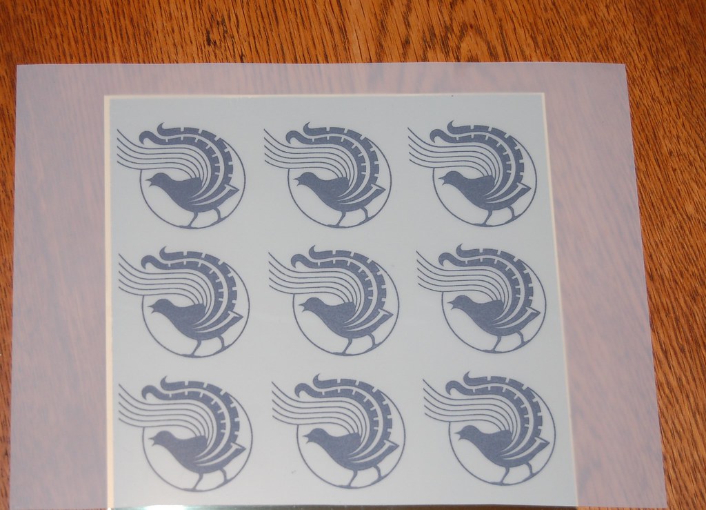

    [url=https://flic.kr/p/GnMebs]Overlay

    The brass sheet is then laminated with photolithographic film, I used DuPont Ristron 500 series. The extra bit of film is to help with judging exposure.
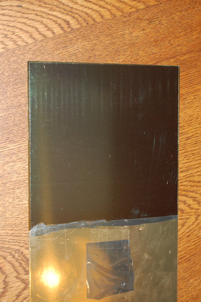

    Brass + film

    The printed sheet is laid ink side down on the film and exposed to UV until the exposed areas crosslink, then a mildly alkaline developer fixes the exposed film whilst loosening the non-exposed areas, creating the mask:
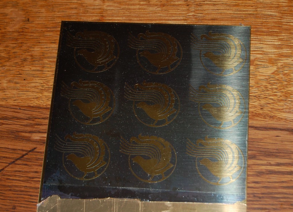
    Etched and Developed by Mark Kelly, on Flickr

    This is etched in iron(III) chloride to 50% of the sheet depth. Note that the previous pics were taken on the first run, the rest are on the second run where I added the border to make dividing the parts easier:
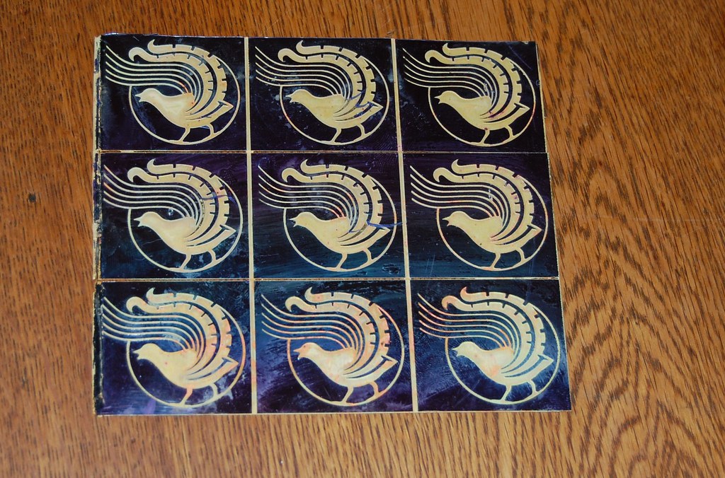

    Etched 2

    The mask is removed with ethanol:
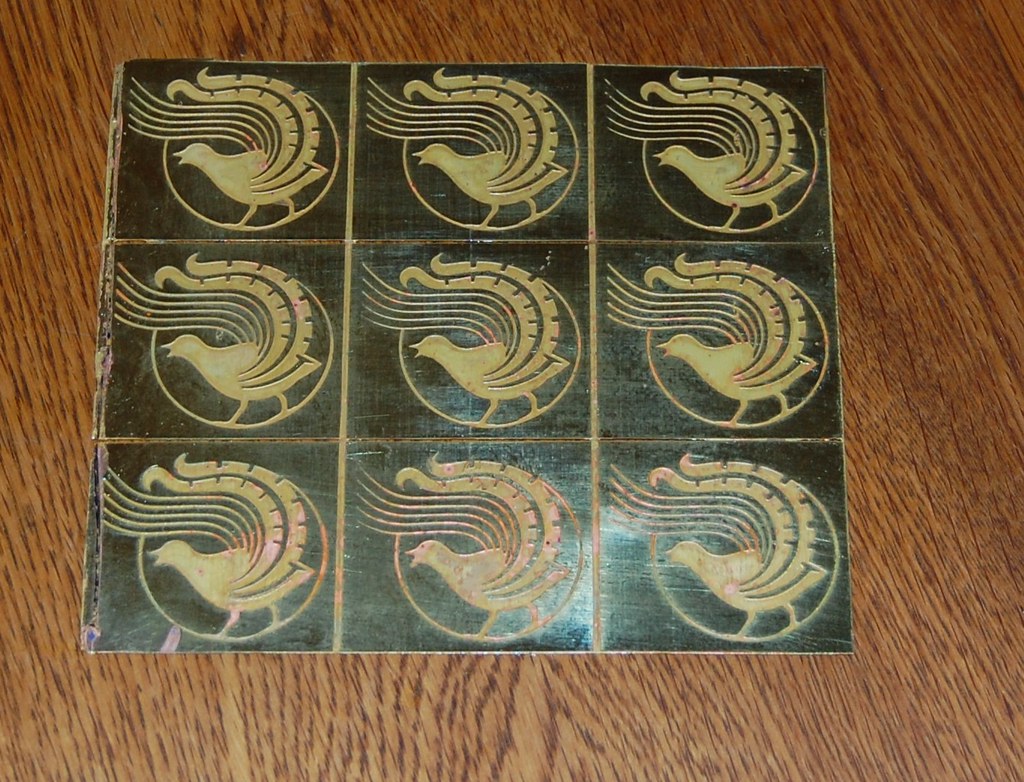

    Stripped

    The sheet is then re-etched for a few minutes to matt down the polished surface. BTW the reason you can see through the borders here is that the back of the sheet is also masked off except at the borders, this helps with judging etch depth (when they meet it's 50% each side) and makes the parts easy to separate.
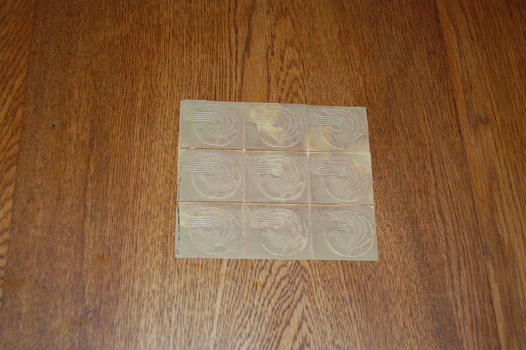

    Re-etched

    The now complete negative is matched up with an equivalent sized piece of silver sheet:
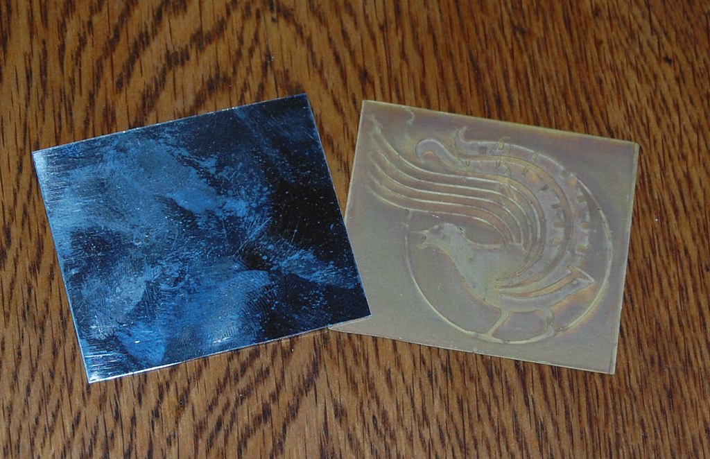

    Silver and Form

    The two are then hand beaten with an ordinary hammer and anvil to force the silver to conform to the milled cavity. Note that the beating causes a bit of deformation at the edges, I actually like this effect:
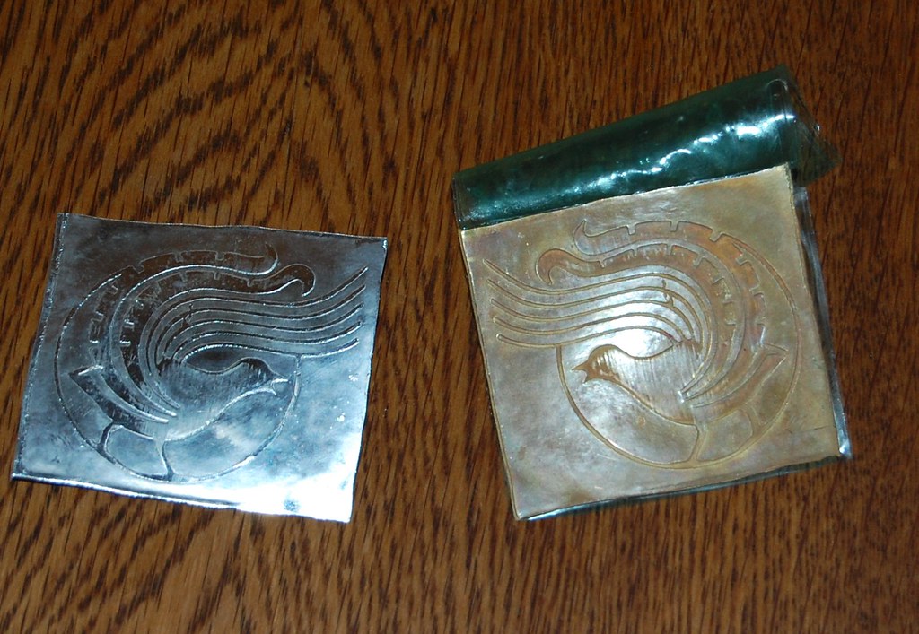

    Silver Formed

    To improve contrast I decided to oxidise the backround using potassium sulphide (KS), known in the jewellery trade as “liver of sulphur”. To prepare the silver for this the sheet is first polished, then the haut relief is burnished with agate, then it is polished again. Finally the haut relief is masked with a resistive ink pen:
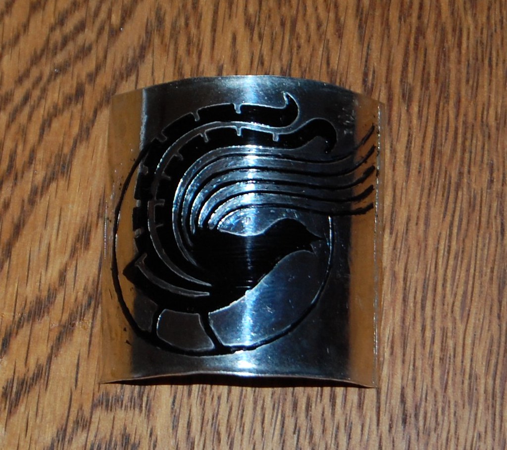

    Masked

    The masked badge is then exposed to the KS solution until the required depth of colour is reached, then neutralised and polished again.

    Enough with the polishing already.

    The final thing does justice to Chooey’s design, which is more than can be said for my terrible photography:
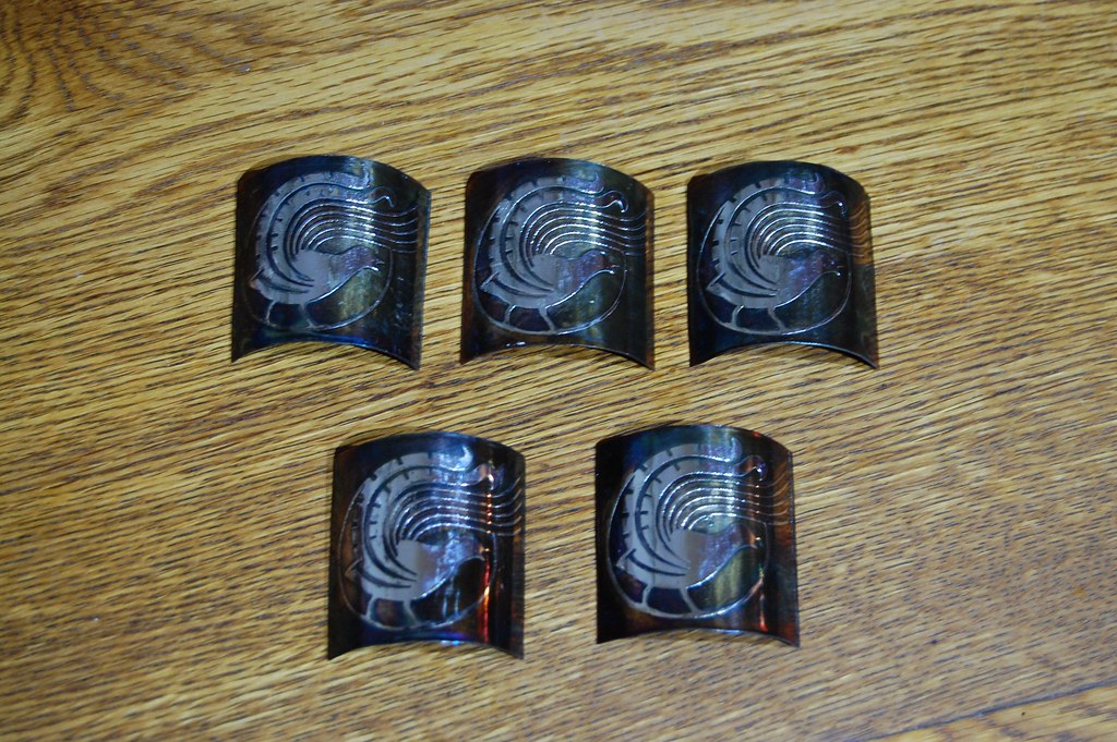

    A Flock of Lyrebirds

    Since I already had the outrageously epxensive 22k gold on hand, I tried adding burnished gold to highlight the display feathers:
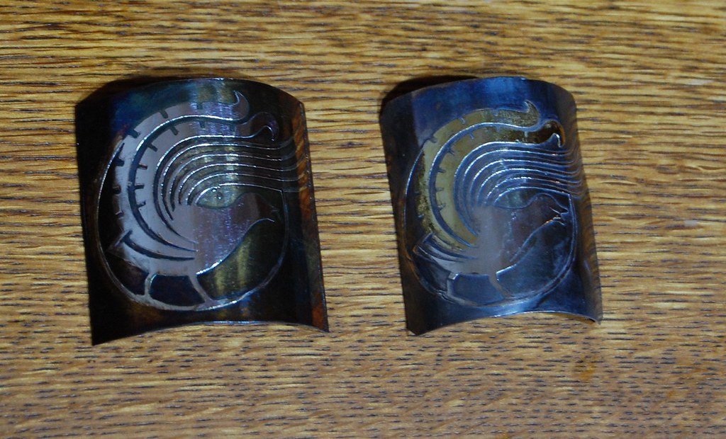

    Silver and Gold

    I'm sticking with the straight silver.
    Mark Kelly

  3. #43
    Join Date
    Aug 2011
    Location
    Beechworth, VIC
    Posts
    2,542
    Post Thanks / Like
    Mentioned
    10 Post(s)
    Tagged
    0 Thread(s)

    Default Re: Headbadge development.

    Something I left out: obviously between the hammering and the sulphide treatment the flat silver is curved to fit the head tube. Since four nines silver is quite soft even when work hardened by hammering, this is done by pressing the piece between a 31.75 mm PMW tube block and a chunk of 30mm aluminium rod.
    Mark Kelly

  4. #44
    Join Date
    Aug 2011
    Location
    Beechworth, VIC
    Posts
    2,542
    Post Thanks / Like
    Mentioned
    10 Post(s)
    Tagged
    0 Thread(s)

    Default Re: Headbadge development.

    K2S, not KS, sorry.
    Mark Kelly

  5. #45
    Join Date
    Jan 2010
    Posts
    386
    Post Thanks / Like
    Mentioned
    0 Post(s)
    Tagged
    0 Thread(s)

    Default Re: Headbadge development.

    Holy crap. Now that's a process. Wow.

    At the end, what are your thoughts? Are ya digging it? Improvements?

  6. #46
    Join Date
    Aug 2011
    Location
    Beechworth, VIC
    Posts
    2,542
    Post Thanks / Like
    Mentioned
    10 Post(s)
    Tagged
    0 Thread(s)

    Default Re: Headbadge development.

    Was that in reference to the bikes or the headbadges?

    Assuming the latter, I'll use what I've got and see how they hold up. I think I will have to protect them from exposure to the elements so I'll use the lacquer I used to use on the brass faceplates of the audio equipment I built. It's called Like Armour and is made by an Australian mining products company called AROA: pdf here.
    Mark Kelly

  7. #47
    Join Date
    Aug 2011
    Location
    Beechworth, VIC
    Posts
    2,542
    Post Thanks / Like
    Mentioned
    10 Post(s)
    Tagged
    0 Thread(s)

    Default Re: Headbadge development.

    K took a few pics of her bike yesterday, here's one.
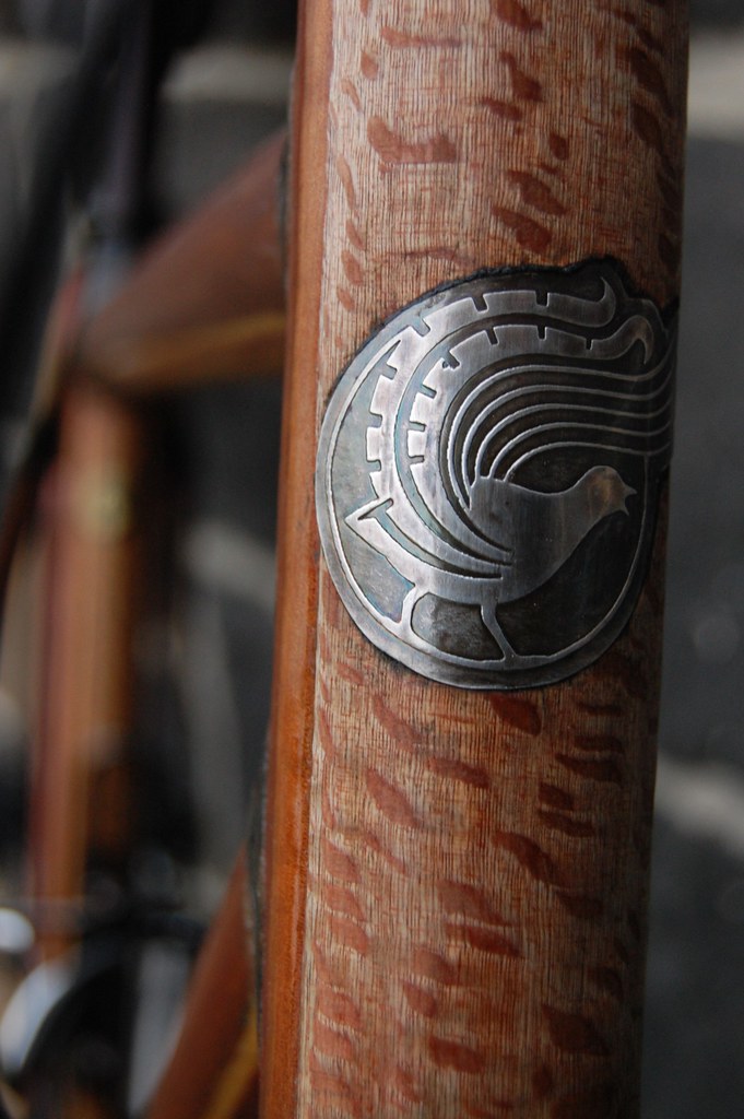

    Mounted
    Mark Kelly

  8. #48
    Join Date
    Aug 2011
    Location
    Beechworth, VIC
    Posts
    2,542
    Post Thanks / Like
    Mentioned
    10 Post(s)
    Tagged
    0 Thread(s)

    Default Re: Headbadge development.

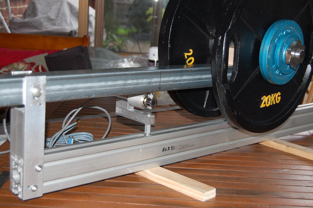
    I'll wirite up a fulle description of the fatigue tester when it's all done and dusted, meanwhile here are a few pics, starting with my Heath Robinsonesque method of checking that the force sensors are reading the right way:


    Calibration Rig

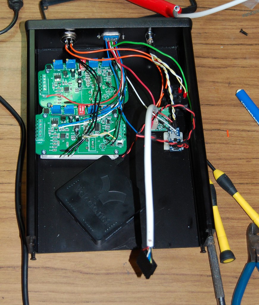
    The force sensors attach to a box with two strain gauge amps, a PLC and some associated power supply stuff:


    Control Box

    Unfortunately the box doesn't look like that any more because I let the smoke out of one of the strain gauge amps today.

    More to follow when I get this fixed.
    Mark Kelly

  9. #49
    Join Date
    Aug 2011
    Location
    Beechworth, VIC
    Posts
    2,542
    Post Thanks / Like
    Mentioned
    10 Post(s)
    Tagged
    0 Thread(s)

    Default Just a pic


    DSC_0246

    Katherine takes pretty good pics using just a phone.
    Mark Kelly

  10. #50
    Join Date
    Aug 2011
    Location
    Beechworth, VIC
    Posts
    2,542
    Post Thanks / Like
    Mentioned
    10 Post(s)
    Tagged
    0 Thread(s)

    Default Jig development again

    In post # 40 above I mentioned that the jig plates have odd sized holes that made alignment more difficult than it could be, and outlined a fix involving conical attachments to the locating screws.

    It didn't work.

    It seems that when the screws are backed out the cones disengage allowing the alignment with the slots to vary. This means the plate can rock enough to interfere with smooth sliding on the extrusion and throw the angular alignment out by about 0.2 degrees. Not a lot, but more than I'm prepared to accept.

    Back to the drawing board, I decided to deal with these two problems separately.

    To line up the holes with the T slots I fabricated some small brass inserts which fit into the holes in the plate and hold the M6 screws centrally.


    Machine tools would have been nice, but I don't have any so I did these with a drill press, a grinder and lots of patience.

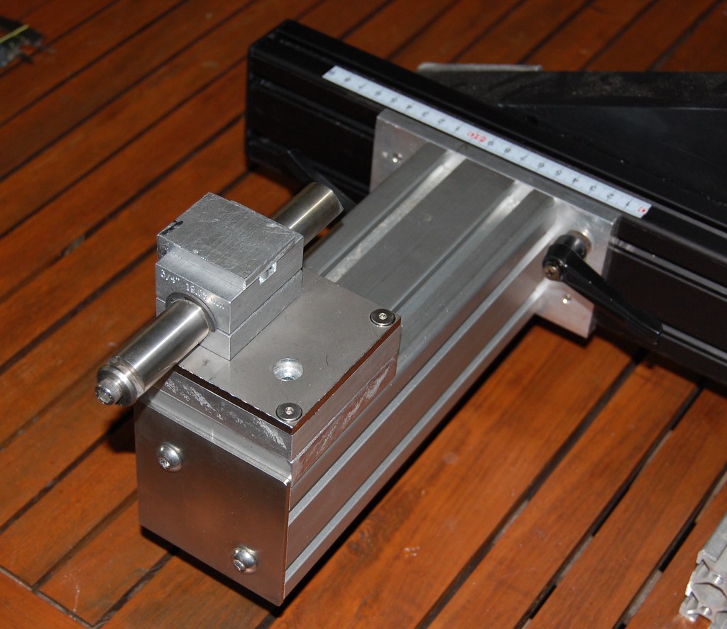
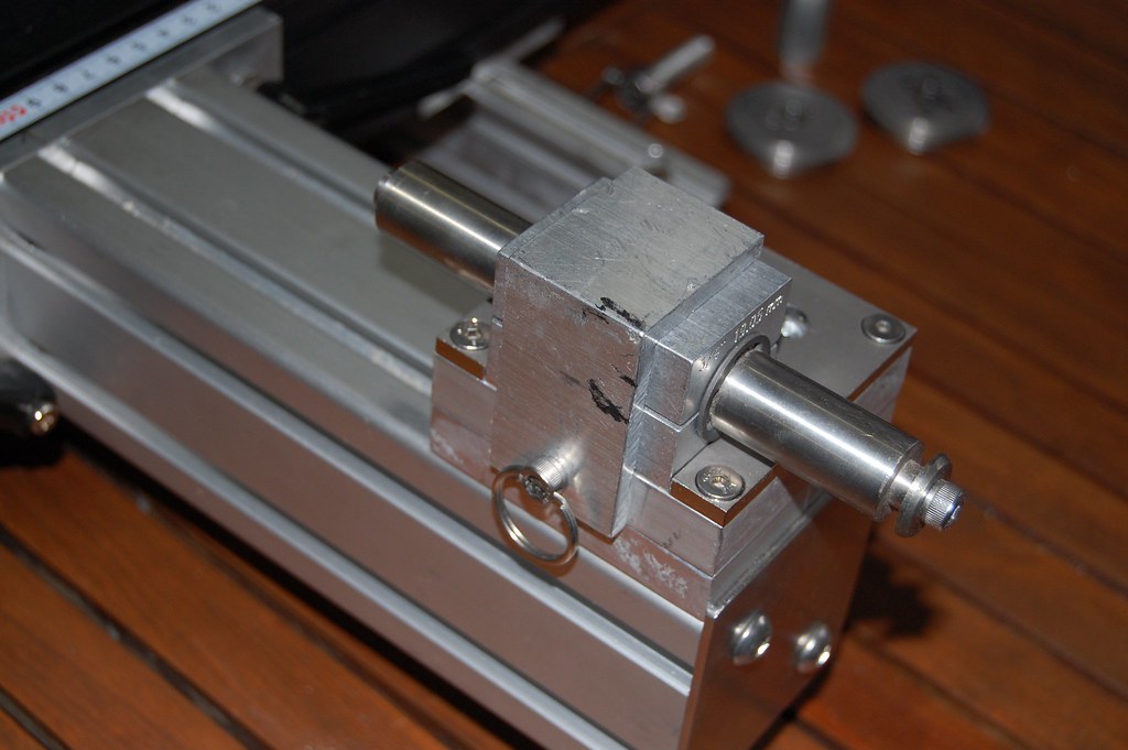
    Next I need to lock the angle of the plate WRT one of the extrusions so I added a linear bearing rail to the extrusion:


    And attached the carrriages to the plate:


    The linear bearing now constrains the motion of the plate so it has only one degree of freedom. The clamping screws hold the plates in alignment in the other two planes and everything lines up nicely

    .

    The jig is now a pleasure to use, holds alignment and is still light enough to lift in and out of the oven.
    Mark Kelly

  11. #51
    Join Date
    Apr 2011
    Location
    Sydney, Australia
    Posts
    5,292
    Post Thanks / Like
    Mentioned
    8 Post(s)
    Tagged
    0 Thread(s)

    Default Re: Jig development again

    Mark - I haven't looked into it yet to check, but... I'm pretty sure I saw a Lyrebird on my ride this morning, in the Ku-Ring-Gai National Park (just north of Sydney). Is that possible / likely?

    And yes, I was on my Lyrebird!

  12. #52
    Join Date
    Aug 2011
    Location
    Beechworth, VIC
    Posts
    2,542
    Post Thanks / Like
    Mentioned
    10 Post(s)
    Tagged
    0 Thread(s)

    Default Re: Jig development again

    Not one of mine.

    There is precisely one person in Sydney with one, and he has two. Hog.
    Mark Kelly

  13. #53
    Join Date
    Apr 2011
    Location
    Sydney, Australia
    Posts
    5,292
    Post Thanks / Like
    Mentioned
    8 Post(s)
    Tagged
    0 Thread(s)

    Default Re: Jig development again

    Erm, I meant the bird...!

  14. #54
    Join Date
    Aug 2011
    Location
    Beechworth, VIC
    Posts
    2,542
    Post Thanks / Like
    Mentioned
    10 Post(s)
    Tagged
    0 Thread(s)

    Default Re: Jig development again

    Ahh, sorry.

    Dunno about Ku-Ring-Gai but I know there's a population in RNP at Audley, so it's at least possible.
    Mark Kelly

  15. #55
    Join Date
    Apr 2011
    Location
    Sydney, Australia
    Posts
    5,292
    Post Thanks / Like
    Mentioned
    8 Post(s)
    Tagged
    0 Thread(s)

    Default Re: Jig development again

    Hmmm, not convinced now - it sort of looked like the pic below (which is a Lyrebird) from memory, but it legged it when I tried to go back for a pic. I recall two distinct tail feathers, but they were more like the whispy ones than the dense, dark ones.


  16. #56
    Join Date
    Aug 2011
    Location
    Beechworth, VIC
    Posts
    2,542
    Post Thanks / Like
    Mentioned
    10 Post(s)
    Tagged
    0 Thread(s)

    Default Re: Jig development again

    Probably a female.
    Mark Kelly

  17. #57
    Join Date
    Aug 2011
    Location
    Beechworth, VIC
    Posts
    2,542
    Post Thanks / Like
    Mentioned
    10 Post(s)
    Tagged
    0 Thread(s)

    Default Lyrebird numbers on the rise.

    The birds, not the bikes.

    Sherbrooke lyrebird research group
    Mark Kelly

  18. #58
    Join Date
    Aug 2011
    Location
    Beechworth, VIC
    Posts
    2,542
    Post Thanks / Like
    Mentioned
    10 Post(s)
    Tagged
    0 Thread(s)

    Default Small coincidences


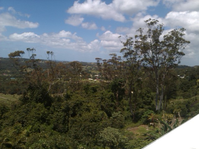
    Mums

    Currently away looking after the Aged P.

    The above pic is from her back verandah, the trees in the foreground are Eucalyptus grandis, my go -to wood for lateral stiffening on the bikes.
    Mark Kelly

  19. #59
    Join Date
    Aug 2011
    Location
    Beechworth, VIC
    Posts
    2,542
    Post Thanks / Like
    Mentioned
    10 Post(s)
    Tagged
    0 Thread(s)

    Default Re: Small coincidences


    Finally got the tester running.
    Mark Kelly

  20. #60
    Join Date
    Aug 2011
    Location
    Beechworth, VIC
    Posts
    2,542
    Post Thanks / Like
    Mentioned
    10 Post(s)
    Tagged
    0 Thread(s)

    Default ISO4210_6 tester


    Slightly better (but still crap) video of tester running.
    Mark Kelly

Similar Threads

  1. Boedie Cycles
    By Boedie in forum Smoked Out
    Replies: 30
    Last Post: 11-22-2014, 05:45 PM
  2. Magnolia Cycles
    By magnoliacycles in forum Smoked Out
    Replies: 25
    Last Post: 04-11-2011, 04:57 PM

Bookmarks

Bookmarks

Posting Permissions

  • You may not post new threads
  • You may not post replies
  • You may not post attachments
  • You may not edit your posts
  •